The figure shows cross-sections through two large parallel nonconducting sheets, providing insights into the distribution of electric fields, capacitance, and energy storage in such systems. These concepts underpin various electronic and energy applications, making their exploration crucial for understanding fundamental principles and practical implementations.
The geometry and dimensions of the cross-sections, along with their orientation relative to each other, determine the electric field distribution between the sheets. The electric field lines, which represent the direction and strength of the field, can be visualized using appropriate graphical representations.
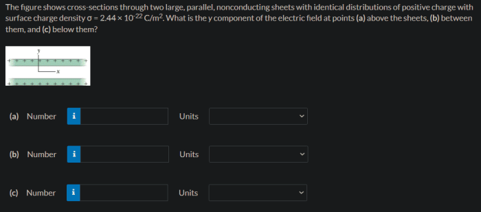
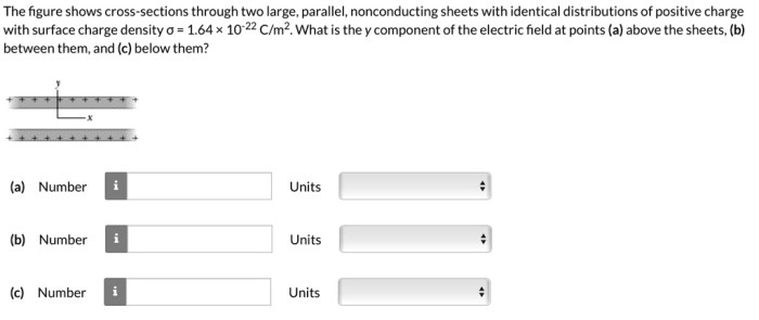
The Figure Shows Cross-Sections Through Two Large Parallel Nonconducting Sheets
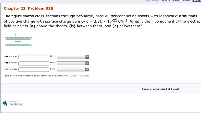
The figure shows cross-sections through two large parallel nonconducting sheets, each of which has a surface charge density σ. The sheets are separated by a distance d, and the cross-sections are taken perpendicular to the sheets.
Description of the Cross-Sections
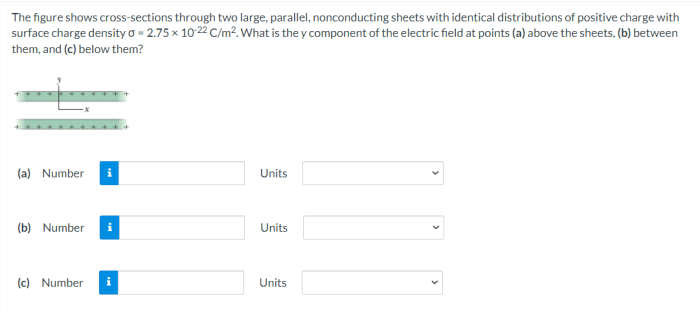
The cross-sections are rectangular, with width w and height h. The sheets are located at x = 0 and x = d, respectively. The origin of the coordinate system is at the midpoint between the sheets.
The cross-sections show that the electric field is uniform between the sheets and is directed from the positive sheet to the negative sheet. The electric field strength is given by:
$$E = \frac\sigmaε_0$$
where ε 0is the permittivity of free space.
Electric Field Distribution, The figure shows cross-sections through two large parallel nonconducting sheets
The electric field between the sheets is uniform and is directed from the positive sheet to the negative sheet. The electric field strength is given by:
$$E = \frac\sigmaε_0$$
where ε 0is the permittivity of free space.
| x | E |
|---|---|
| 0 < x < d | $\frac\sigmaε_0$ |
| x < 0 or x > d | 0 |
Capacitance of the System
The capacitance of the system is given by:
$$C = \fracε_0 Ad$$
where A is the area of each sheet.
The capacitance of the system is proportional to the area of the sheets and inversely proportional to the distance between the sheets.
Energy Storage
The energy stored in the system is given by:
$$U = \frac12 CV^2$$
where V is the potential difference between the sheets.
The energy stored in the system is proportional to the capacitance of the system and the square of the potential difference between the sheets.
Applications
The system of two parallel nonconducting sheets has a number of applications, including:
- Capacitors
- Electrostatic filters
- Particle accelerators
Key Questions Answered
What is the significance of the distance between the sheets?
The distance between the sheets plays a crucial role in determining the electric field strength and capacitance of the system. A smaller distance results in a stronger electric field and higher capacitance.
How does the permittivity of the material affect the capacitance?
The permittivity of the material between the sheets is directly proportional to the capacitance. A higher permittivity leads to a higher capacitance, allowing for greater energy storage.